In this article, we will learn how to create custom objects in SharpShooter Diagrams and review the particularities of this process. To demonstrate it on a sample, we will create a simple object showing Sun (the delivery package of the component includes the Sun class, but we are going to write our own class – UserSun). Let’s start from the declaration:
public class UserSun : SquareTextBlockBase
{
}
Here, please pay attention to the StoredClass attribute. It is required for serialization of the object. As a parameter, we need to pass some unique value by which the object will be restored from the serialized data. The SquareTextBlockBase class is taken as a base class. For most objects, we recommend using the TextBlockBase class, but within our project we will create a square object. The SquareTextBlockBase is an inheritor of the TextBlockBase and it adds some issues specific for square objects. TextBlockBase is a base class for many objects and represents a marquee in which you put down a figure. It supports a text legend and drawing in internal coordinate system.
Ok, let’s continue describing our class. For drawing, we need to write the DrawContent method:
public class UserSun : SquareTextBlockBase
{
protected override void DrawContent(IDrawingContext context)
{
}
}
As we can see, the method gets the only parameter – IDrawingContext. This special interface provides comprehensive facilities for objects drawing. It looks the following way:
{
// Geometry
void DrawRectangle(Vector2D location, Vector2D size, double cornerRadius, FillPattern fill, Pen pen);
void DrawEllipse(Vector2D location, Vector2D size, FillPattern fill, Pen pen);
void DrawLine(Vector2D startPoint, Vector2D endPoint, Pen pen);
void DrawPolygon(IEnumerable points, FillPattern fill, Pen pen);
void DrawPolyline(IEnumerable points, Pen pen);
void DrawGeometry(DrawingGeometry geometry, FillPattern fill, Pen pen);
// Text
void DrawText(string text, Rectangle2D bounds, VAlign vAlign, TextAlign textAlign, Font font, FillPattern textFill, FillPattern textBackground);
void DrawText(string text, Vector2D position, Vector2D textPivot, TextAlign textAlign, Font font, FillPattern textFill, FillPattern textBackground);
// Image
void DrawImage(ImageData image, Vector2D location, Vector2D size, PictureScaleMode mode);
// Objects
object DrawDirect(Func objectToInsert);
// Push/Pop
void PushTransform(AffineTransform transform);
void PushOpacity(double opacity);
void PushTranslator(DrawingContextTranslator translator);
void Pop();
}
By passing various implementations of this interface we can build diagram visualization in any format, For example, the SilverlightDrawingContext allows displaying shapes in a Silverlight application, and the SvgDrawingContext allows implementing export to a SVG format. Using the Push/Pop methods we can influence drawing some specific primitives. For example, with the help of the PushTransform method we can implement moving the internal coordinate system of the TextBlockBase class to the global coordinates of the whole page. And with the help of the PushTranslator method, the Sketch style is implemented (drawing of all lines is formatted as a freehand drawing style). Using the DrawDirect method we can put various Silverlight objects (buttons, check boxes, etc) into a diagram.
Drawing using the methods directly from the IDrawingContext is not handy in some cases. To simplify drawing, there is the DrawingExtensions class – a static class that contains dozens of the methods-extensions for objects providing opportunity to shorten syntax. Let’s take advantage of these methods for drawing our Sun. Let’s assume that a sun always consists of yellow disc and beams coming from it (beams will be filled with the color defined in the Fill property). Now, we will describe the drawing process:
public class UserSun : SquareTextBlockBase
{
#region Visualization
protected double GetRayAngle(int index)
{
return 2 * Math.PI / RayAmount * index;
}
protected override void DrawContent(IDrawingContext context)
{
Vector2D center = Size / 2;
this.DrawCircleByCenter(context, center, AbsoluteCenterRadius, new SolidFill(Colors.Yellow));
for (int i = 0; i < RayAmount; i++)
DrawRay(context, center, GetRayAngle(i));
}
private void DrawRay(IDrawingContext context, Vector2D center, double angle)
{
Vector2D p1 = center + Vector2D.FromPolar(Radius, angle);
Vector2D p2 = center + Vector2D.FromPolar(Radius * (RelativeCenterRadius + 0.1), angle + Upsilon);
Vector2D p3 = center + Vector2D.FromPolar(Radius * (RelativeCenterRadius + 0.1), angle - Upsilon);
this.DrawPolygon(context, new[] { p1, p2, p3 });
}
#endregion
}
As you can see from the code above, a sample uses some properties which have not been declared yet. Let’s pay special attention to the radius of the sun itself, without considering its beams yet. Let’s describe the class to provide a user with the ability to change the radius. To do this, the corresponding property must be described the way to correctly serialize it. Description format is similar to DependencyProperty in Silverlight, but its syntax is more minimalistic:
[AutomatedProperty(DefaultValue = 0.5, IsNotNull = true)]
[UpdatesVisuals]
[UpdateConnections]
public double CenterRadius
{
get
{
return (double)GetValue(CenterRadiusPropertyKey);
}
set
{
SetValue(CenterRadiusPropertyKey, value);
}
}
public double RelativeCenterRadius
{
get
{
return MathUtilities.Clamp(CenterRadius, 0.1, 0.8);
}
set
{
CenterRadius = MathUtilities.Clamp(value, 0.1, 0.8);
}
}
public double AbsoluteCenterRadius
{
get
{
return RelativeCenterRadius * Radius;
}
set
{
if (Math.Abs(Radius) > MathUtilities.Eps)
RelativeCenterRadius = value / Radius;
}
}
Property storage is performed using the CenterRadiusPropertyKey/CenterRadius pair, and to make it more convenient, we create additional properties: RelativeCenterRadius, AbsoluteCenterRadius (they provide access to a property taking into account values adjustments, while the CenterRadius just provides access to the property). Many properties of standard objects are created following that scheme. Besides, let’s describe a pair of supporting properties to display our object:
{
get
{
return Math.PI / 10.0;
}
}
protected int RayAmount
{
get
{
return 8;
}
}
The first version of the object is ready. Now we can add the element on the ToolBox to see how it looks like:
{
Items =
{
new ToolboxCategory("Test")
{
Items = { new PrototypeToolboxItem("Sun", new UserSun { Size = new Vector2D(32, 32) }) }
}
}
};
toolbox.Model.Groups.Clear();
toolbox.Model.Groups.Add(customGroup);
toolbox.Model.CurrentGroup = customGroup;
toolbox.Model.UpdateSearchAutocompleteList();
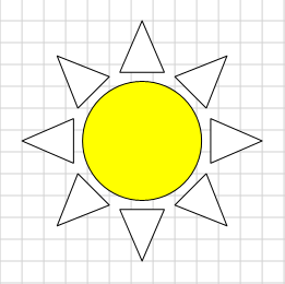
Modified SharpShooter Diagrams Element
As we can see, the sun disc is colored in yellow, and the beams are still white – it is the default color for all shapes. Let’s rewrite a little bit composition of the ToolBox so we will have several suns with beams of different colors. But instead of using fill settings, we will choose the use of styles. Each element has a special property – StyleName, that contains a style name. If we do not set a value of some property (for example, the color), it is taken from the selected style. The main advantage of this approach is that if we set a style we can simultaneously change the display parameters of all objects with the same style without the necessity to change them one by one (to do this we just need to change the theme using the Themes property in the DesignerModel class). Names for most of the standard styles can be seen in the static constants of the ThemeBuilder class. And here, we will create 8 objects with 8 standard styles: “Node 1″ .. “Node 8″:
ToolboxCategory category = new ToolboxCategory("Test");
for (int i = 1; i <= 8; i++)
category.Items.Add(new PrototypeToolboxItem("Sun " + i, new UserSun { Size = new Vector2D(32, 32), StyleName = "Node " + i}));
Below you can see all the objects we created in different standard themes:
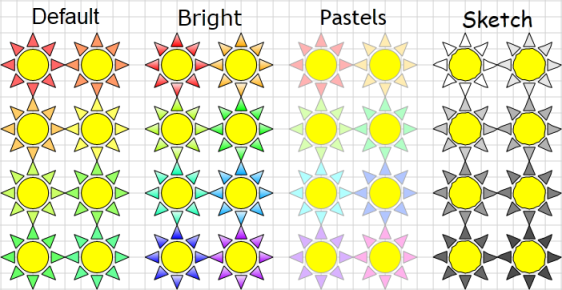
Application of Different Themes
Let’s continue improving our shape. Let’s provide a user with the ability to edit the CenterRadius parameter. To do this we need to override the formation of the Adorners for our object. To implement any additional behavior it is needed to write an additional class. For our specific task, the required class will look the following way:
public class UserSunAdornersProvider : AdornersProvider
{
public override void GetAdorners(UserSun element, IList adorners)
{
base.GetAdorners(element, adorners);
this.AddAdornerPoint(adorners, element, GetControlPoint, SetControlPoint, "Location,Size,Rotation");
}
public Vector2D GetControlPoint(UserSun element)
{
return element.ToExternalCoords(element.Size / 2 + new Vector2D(element.AbsoluteCenterRadius, 0));
}
public void SetControlPoint(UserSun element, Vector2D value)
{
element.AbsoluteCenterRadius = Math.Abs(element.ToInternalCoords(value).X - element.Size.X / 2);
}
}
In this example we create an inheritor from the AdornersProvider generic class which is marked with special attribute (to make the component understand that this class overrides generation of the objects for our UserSun). As the second line of the GetAdorners we add a new Adorner. To do this we need to specify the following: list of the adorners adorners, the element element itself, the GetAdorners method to get Adornder’s coordinates, the SetAdorners method to overwrite Adorner characteristics after user manipulations, and also a list of triggers which defines a list of properties after changing which it is required to renew Adorner characteristics (in our case they are 3 properties which define object position). Please note that Adorner position must be indicated in global coordinates. To do this we will take advantage of the ToInternalCoords, ToExternalCoords methods defined in the TextBlockBase class. So now a user has an opportunity to change object’s geometry.
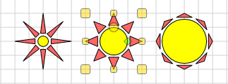
Changing Objects Geometry
Let’s review one more issue of the shape description – ports. Ports are special objects which allow connecting shapes using arrows. Currently, the sun has 4 ports inherited from the SquareTextBlockBase class. We delete old ports and add a port on the end of each beam of the sun. To do that we need to override the RegisterPorts method in the UserSun class. To add a new port it is required to specify the following values: port name, a delegate to get port coordinates, and port angle:
{
base.RegisterPorts();
Ports.Clear();
for (int i = 0; i Size / 2 + Vector2D.FromPolar(Radius, angle), GeometryUtilities.ConvertToDegrees(angle));
}
}
Now, when we mouse over the object we can see the ConnectionAdorner on each angle of our sun.
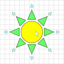
Object Adorners
As a result, we get a working full-featured element. You can download the full source of the element here: UserSun.cs